
I’m hacking my coffee maker. I routinely set it up for the morning so that I can just get up and hit the button, but I want to take that further. The goal here is to utilize an ESP8266 to connect to the internet and when given a signal, trigger a MOSFET to turn the coffee maker on. The signal can either be Alexa or set to a specific time. Analyzing the internal electronics, the 110V AC wall power is converted to an internal 5V DC for the logic circuitry. The coffee maker does turn itself off when the all the water is gone so an initial “turn on” signal on the 5V line in parallel with the switch should suffice.
To create our Alexa-controlled switch I can use an ESP8266. These devices connect to WiFi and can be loaded with simple sketches that control, in this case, the HIGH/LOW status of the 3.3V output pins. I use the output pin to control the gate of an N-channel MOSFET with the drain connected to the coffee’s 5V line and the source to the grounded side of the switch. When the ESP sends the 3.3V signal to the gate, the MOSFET conducts and the 5V side of the switch is pulled to ground, triggering the coffee maker. I use a 220Ω series resistor to limit any current spikes when the output pin is triggered, and a 10kΩ resistor to ground so that when not enabled the gate doesn’t float but is pulled to ground.
I had originally planned on powering the ESP directly from the 5V line, but initial testing showed that the ESP drew too much current causing the voltage to drop, preventing the circuit from functioning as intended. It is far less elegant, but I relented and ran a separate micro-usb cable to power the ESP independently. The upside is that plugging the ESP into an outlet gives a stable 5V line and offers an easy way to update or change the sketch in the future if necessary.
Here’s the schematic of the circuit and layout of the PCB I used to control my coffee maker.
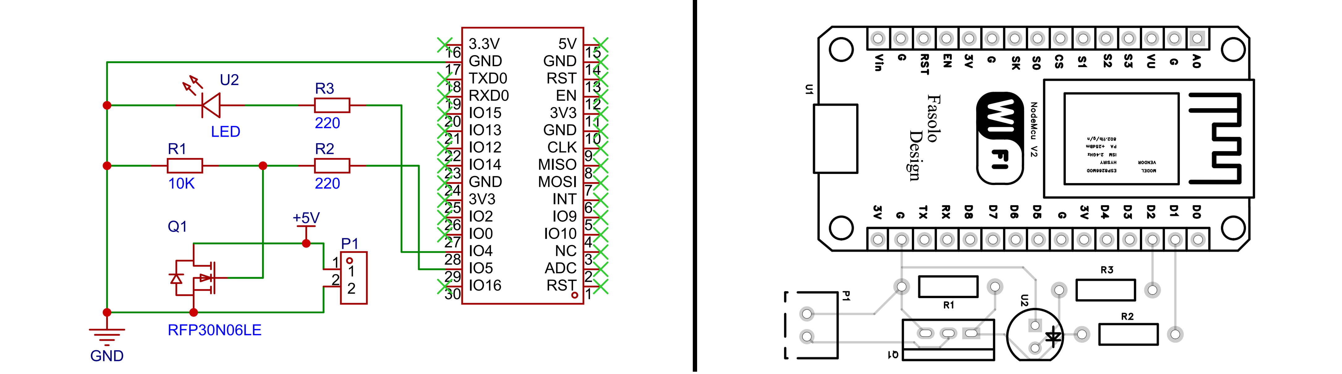 Alexa enabled coffee maker circuitry and PCB (made with EasyEDA)
The micro-usb plugs into the ESP (U1), and the PCB output interconnect (P1) runs to the 5V and Ground side of the coffee maker switch.
To trigger the coffee maker I just needed to have the ESP listen for commands from Alexa. For this I use the fauxmoESP.h library. This makes the device discoverable by Alexa by having it mimic a WiFi power plug so Alexa can send it On/Off commands (and nothing more complicated- more on that later). Here’s the sketch I uploaded:
#include <fauxmoESP.h>
#include <ESP8266WiFi.h>

#define WIFI_SSID     <wifi network name>
#define WIFI_PASSWORD <wifi password>


fauxmoESP fauxmo;

const int RELAY_PIN = D1;  // GPIO pin controlling the MOSFET
unsigned long lastTriggerTime = 0;
unsigned long pulseStartTime = 0;
bool pulseActive = false;
const unsigned long cooldownPeriod = 10000; // 10 seconds
const unsigned long pulseDuration = 3000;  // pulse duration

const int LED_PIN = D2;  // GPIO pin controlling LED indicator
bool ledState = false;

void setupWiFi() {
  delay(3000);
  WiFi.mode(WIFI_STA);
  WiFi.begin(WIFI_SSID, WIFI_PASSWORD);
  Serial.print("Connecting to WiFi");
  while (WiFi.status() != WL_CONNECTED) {
    ledState = !ledState;  // switch LED state
    digitalWrite(LED_PIN, ledState ? HIGH : LOW);
    Serial.print(".");
    delay(250);
  }
  digitalWrite(LED_PIN, HIGH);
  Serial.println("\nWiFi connected. IP: " + WiFi.localIP().toString());
}

void setup() {
  Serial.begin(115200);
  pinMode(RELAY_PIN, OUTPUT);
  digitalWrite(RELAY_PIN, LOW);
  pinMode(LED_PIN, OUTPUT);
  digitalWrite(LED_PIN, LOW);

  setupWiFi();

  fauxmo.createServer(true);   // Required for gen3+ Echo devices
  fauxmo.setPort(80);          // Set to 80 for Echo discovery
  fauxmo.enable(true);

  fauxmo.addDevice("coffee maker");

  fauxmo.onSetState([](unsigned char id, const char *name, bool state, unsigned char value) {
    if (strcmp(name, "coffee maker") == 0 && state) {
      pulseStartTime = millis();
      if (pulseStartTime - lastTriggerTime >= cooldownPeriod) {
        Serial.println("Coffee Maker: Triggering HIGH pulse");
        digitalWrite(RELAY_PIN, HIGH);
        pulseActive = true;
        lastTriggerTime = pulseStartTime;
      } else {
        Serial.println("Coffee Maker: Ignored trigger (cooldown active)");
      }
    }
  });
}

void loop() {
  fauxmo.handle();

  if (pulseActive) {
    if (millis() - pulseStartTime >= pulseDuration) {
      digitalWrite(RELAY_PIN, LOW);
      pulseActive = false;
    }
  }
}
When powered, the void setup() sets the relay pin as an output, sets it to low (to ensure the gate is not being triggered), then connects to WiFi. Then fauxmo gets to work creating the device “coffee maker” and setting the “on-state” condition. This is where, when getting the “turn-on” signal from Alexa, I execute a 3 second HIGH pulse to the output pin. I also instituted some code to set a cooldown period of 10 seconds to prevent any multi-trigger events. After loading this sketch onto the ESP and plugging in the external 5V power source, I can talk to Alexa and ask her to discover new devices. She then finds “coffee maker,” after which it appears in my connected devices list (note it shows up as a Royal Phillips Electronics device since it “looks” like a smart home wall plug or bulb because of what fauxmo is doing). Then I can simply ask Alexa to turn on “coffee maker.” Here I took it one simple step further and created a routine, that way I can give it a custom command. In my case, I say “Alexa, make me coffee” and she triggers the ESP and responds “hot bean water, coming right up.”
Next step: As mentioned, the fauxmo library enables this smart-home automation, but is limited to On/Off commands since we’re emulating a smart wall plug. I’d like to move into using Home Assistant, hosted on something like a Raspberry Pi, as the hub of smart-home devices, then connect the ESP to the hub by installing ESPHome on the ESP board. With this setup, I’d connect any smart devices to the Home Assistant, then manage that online via a dashboard. The plus sides are both that I can connect as many devices in the future as I want without having to connect each of them to Alexa individually, but more importantly because each of those devices can handle much more complex instructions. In the coffee maker’s case, I’d like to make the coffee maker into a true smart device. If I implement a water-level sensor, the coffee maker could receive the turn-on command from the hub, then run logic checks to ensure there’s actually water in the tank- if yes, turn it on, or if not, it could tell the hub there’s no water, and the hub could trigger Alexa to reprimand me for not setting up the coffee the night before! Much more responsive, and a true smart-home device.
But at least for now, I can turn on my coffee maker anywhere in the house that Alexa can hear me!